ESP8266

The ESP8266 is a low-cost Wi-Fi chip developed by Espressif Systems. It can be used as a standalone device, or as a UART to Wi-Fi adaptor to allow other microcontrollers to connect to a Wi-Fi network. For example, you can connect an ESP8266 to an Arduino to add Wi-Fi capabilities to your Arduino board.
ESP8266 是由 Espressif Systems 开发的微控制器芯片。它是一款高度集成的无线系统芯片(SoC),专为低成本、低功耗和空间受限的应用而设计。它包括一个32位微控制器单元(MCU)和一个16位短模式,并支持 80MHz 和 160MHz 的时钟速度。ESP8266 还内置了 Wi-Fi 功能和完整的TCP/IP协议栈,适用于物联网(IoT)和其他嵌入式 Wi-Fi 应用。
这使得它可以很方便地作为执行单元通过网络控制 IO 接口的高低电平信号。
这里我们首先要搞清楚的一些事实是,ESP8266 只是一个微控制器芯片,在这个语境下是不包含外围电路和天线的,只是一颗芯片而已,它无法独立工作。 那么为了能让其正确工作,我们需要为它提供必要的外围电路,这就衍生出了不同的模块和开发版。
常见的封装有:
- ESP-01/ESP-01S
- ESP-12E/ESP-12F/ESP-12S
- NodeMCU Kit (内部使用了 ESP-12E)

ESP-01 / ESP-01S

The ESP-01 is on the left, and the ESP-01S is on the right. The ESP-01 includes two LEDs near the PCB antenna, one for the Tx line (GPIO1) and the other for the power indicator. The ESP-01S, on the other hand, has only one Blue LED and is wired to GPIO2. Two more pull-up resistors were added to the ESP-01S, which can be seen between the ESP8266EX chip and the header pins. Between the CH PD and 3v3 (VCC) pins is one of the pull-up resistors.
ESP-01位于左侧,ESP-01S位于右侧。ESP-01包含两个位于PCB天线附近的LED,一个用于Tx线(通常连接到GPIO1),另一个用于电源指示灯。另一方面,ESP-01S只有一个蓝色LED,并连接到 GPIO2。ESP-01S还添加了两个上拉电阻,可以在ESP8266EX芯片和引脚头之间看到。在CH PD和3.3V(VCC)引脚之间有一个上拉电阻。
这两者的区别在于硬件配置。ESP-01和ESP-01S都是基于ESP8266芯片的WiFi模块,但它们在LED配置和上拉电阻方面存在差异。这些差异可能会影响如何配置和使用GPIO引脚以及在项目中的特定用途。
ESP-12E、ESP-12F、ESP-12S 的区别
ESP-12E
ESP-12E 是一种具体的 Wi-Fi 模块,它使用 ESP8266 作为其核心处理器。这个模块是由 Ai-thinker 团队开发的。ESP-12E 封装了 ESP8266 SoC,并提供了额外的组件,如 Wi-Fi 天线、板上的射频(Radio Frequency)组件以及其他必要的电路,以便开发人员更容易地将 Wi-Fi 功能集成到其项目中。它遵循 IEEE802.11 b/g/n 标准,可以用于向现有设备添加 Wi-Fi 网络功能,或创建独立的网络控制器。
The following figure illustrates the ESP8266 12-E chip pinout. Use this diagram if you’re using an ESP8266 bare chip in your projects.
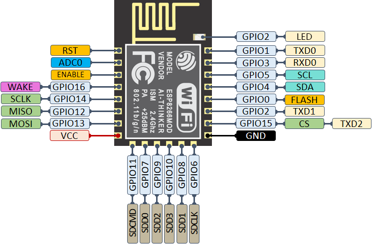
source: randomnerdtutorials and aahgo
ESP-12 WiFi 模块有多个不同的子版本,包括 ESP-12E, ESP-12F 和 ESP-12S。它们的区别是什么呢?
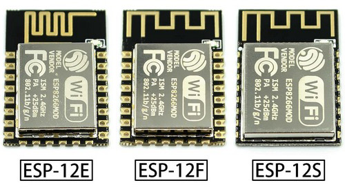
ESP-12E 使用的 PCB 板层为两层。ESP-12F 使用的 PCB 板层为四层,而且重新设计了板载天线,使用上更加稳定。
ESP-12S 在 ESP-12F 的基础上将 GPIO0、GPIO15、RST、EN 引脚进行了内部上下拉处理,接线上只需要接四根线就可以正常使用。去掉了 ESP-12E/12F 尾部的 9-14 引脚,这些引脚已经被板载 Flash 芯片占用了,本来也基本无法使用。
ESP-12F 原理图
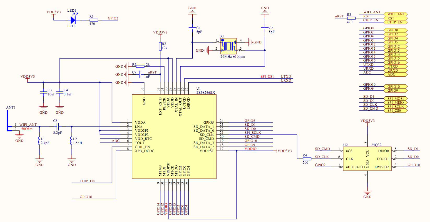
ESP-12S 原理图
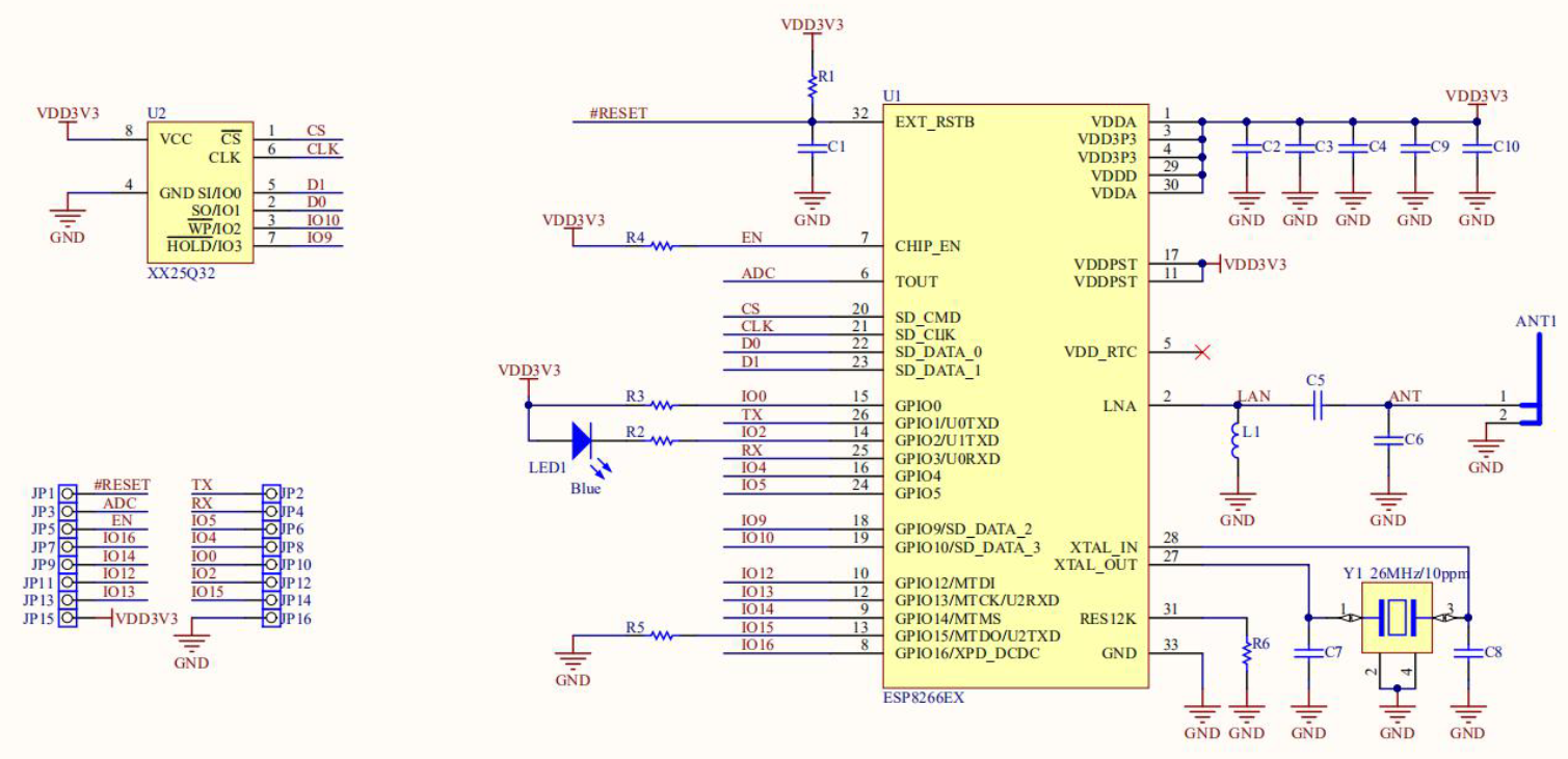
在 安信可科技 的网站上我找到了更全面的对比:ESP8266系列模组专题
NodeMCU Kit

实际上,NodeMCU 就是使用了 ESP-12E 作为核心的开发板。
Flash
esptool.py --port /dev/cu.usbserial-7152051CB6 write_flash 0x10000 ~/Downloads/m5stick-c-20240317.bin
https://docs.espressif.com/projects/esptool/en/latest/esp8266/esptool/basic-commands.html
控制 LED 灯
#include <Arduino.h>

void setup()
{
  pinMode(LED_BUILTIN, OUTPUT);
}

void loop()
{
  digitalWrite(LED_BUILTIN, HIGH);
  delay(1000);
  digitalWrite(LED_BUILTIN, LOW);
  delay(1000);
}
https://github.com/lsongdev/esp8266-basic
通过网络控制 LED 灯
我推荐使用 MQTT 的方式控制,代码参考这里:
https://github.com/lsongdev/esp8266-mqtt/blob/master/src/main.cpp
ESP8266 DHT

https://github.com/lsongdev/esp8266-dht
ESP8266 Relay
目前市面上存在两种继电器,一种使用 IO 控制,另一种使用串口控制。
| IO控制 | 串口控制 |
|---|---|
 |
 |
IO控制的要用 GPIO0 低电平触发 https://github.com/lsongdev/esp8266-relay
串口控制要发送一段数据:
void relay_open() {
  byte open[] = {0xA0, 0x01, 0x00, 0xA1};
  Serial.write(open, sizeof(open));
}

void relay_close() {
  byte close[] = {0xA0, 0x01, 0x01, 0xA2};
  Serial.write(close, sizeof(close));
}
完整代码参考:https://github.com/lsongdev/esp8266-relay-stc15f104w
ESP8266 双路继电器

| IO | Description |
|---|---|
| IO0 | - |
| IO2 | Builtin LED |
| IO4 | RY2 |
| IO5 | RY1 |
| IO16 | LED0 |
https://github.com/lsongdev/esp8266-relay2
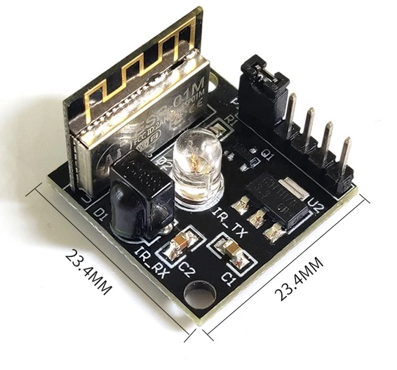
ESP_IR_TR
ESP8266 Matrix
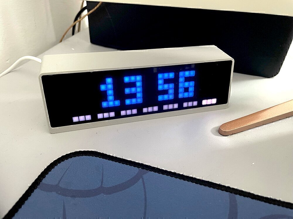
https://github.com/lsongdev/esp8266-matrix
ESP8266 TFT Display

屏幕使用 ST7789 芯片,可以使用 TFT_eSPI 库来控制。
但是这个屏幕似乎有点区别,需要修改代码:
一个是它的背光控制,似乎是可以支持背光调节的,TFT_eSPI 默认的背光是拉高的,这个屏幕是拉低的。
另外就是在屏幕初始化阶段,需要屏蔽掉代码中的 ST7789_COLMOD=0x55 命令。
修改完这两处就可以正常驱动了。
#include <SPI.h>
#include <TFT_eSPI.h>

TFT_eSPI tft = TFT_eSPI();

void setup()
{
  tft.init();
  tft.setTextSize(3);
  tft.setCursor(0, 0);
  tft.println("Hello World!");
}

void loop()
{
}
https://github.com/lsongdev/esp8266-tft